Email:
hieuchuan3d@gmail.com


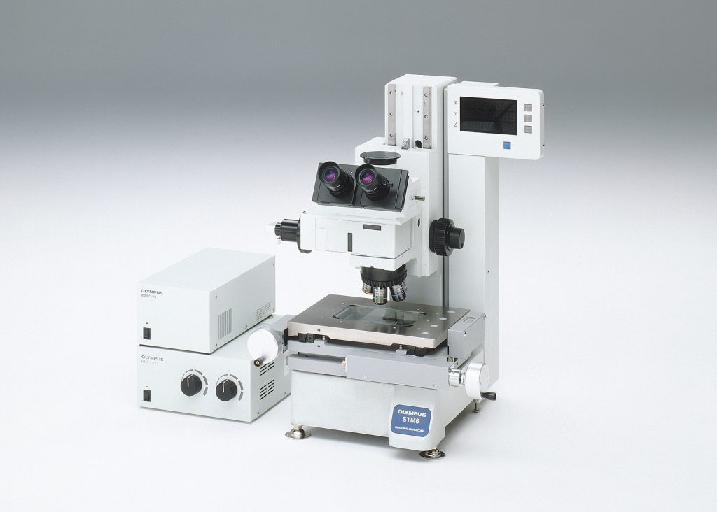
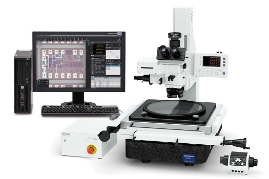
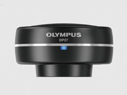
The ability to clearly and easily see the output display component of measuring microscopes is essential. That is why the new Olympus measuring software has been created, helping to deliver complex measurements with greater accuracy. The software also enables the use of digital cameras.
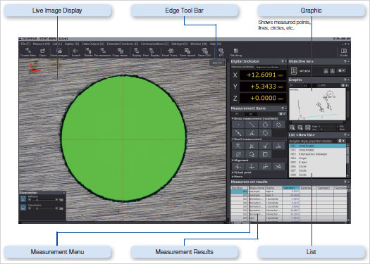 STM7-BSW Sample GUI
1920 x 960
2448 x1920
Frame rate
30fps (1920 x 960)
15fps (2448 x1920)
PC interface
USB3.0
960 x 720
1920 x 1440
Frame rate
25fps
PC interface
USB3.0
1024 x 768
2048 x 1536
Frame rate
11.2fps (max.)
PC interface
USB2.0
Measurements are made by receiving coordinates input via STM7.

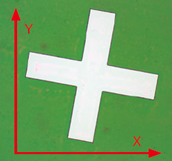 Original axis
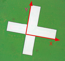 New axis
Conventional measuring microscopes measure the XY plane directly from above. However in response to user demands, Olympus has incorporated an XZ plane measurement function in the STM7-BSW to enable the measurement of crosssections as seen from the side. Now measurements that used to be diffi cult are much easier—such as radius measurements for vertical sections of hemispherical objects, or measurement of the depths of grooves with curved bases compared to a reference line.
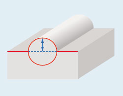 R measurement of a hemispherical sample
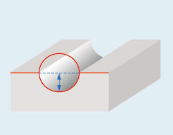 Height measurement of a groove from its base and the reference line
Frequently used alignment and other measurement procedures can be combined and assigned to a single macro button—eliminating the need to start from scratch each time the microscope is set up.
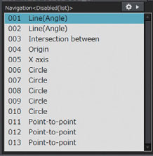
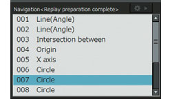
Measurements can be easily repeated based on a recorded workflow by simply inputting the movement of the stage and the coordinates in response to a software prompt. This function can be used to repeatedly carry out the same measurement on the same sample, or diff erent versions of the same sample.
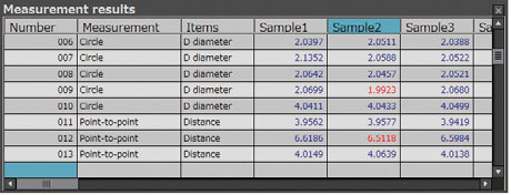
Furthermore, if a set value and tolerance are set in the recorded workfl ow, the software can automatically identify when a measurement has failed.
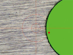
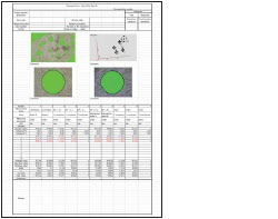
This function detects the edges of the sample and automatically acquires and measures its coordinates. As a result, operators no longer need to designate the coordinates and subjectivity is minimized. Automatic Edge Detection also features a timer function that enables coordinates to be acquired in a specified time and supports the use of a foot switch that enables the operator to focus on measurement operations without taking his or her hands off the stage handles.
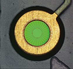 Automatic edge detection inside the circle
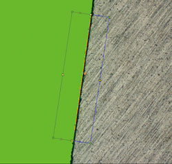 Multiple points automatic edge detection
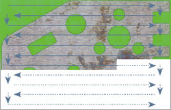
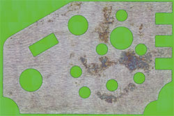
Metal burrs and other abnormal points can be excluded automatically during edge detection. This enables a consistent calculation of measured values, irrespective of the state of the sample. Points excluded as abnormal can also be displayed on the screen in diff erent colors.
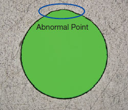 Sample with abnormal point
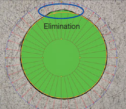 Abnormal point elimination
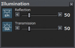
The light intensity of the microscope can be maintained by accurate software control. Light intensity settings can also be saved when recording a workfl ow for replay measurement, enabling measurements to be made under the same conditions during replay measurements or automatic edge detection.
Through use of the coded revolving nosepiece, previously set calibration values are automatically recalled when changing the objective. In this way, the user can always be confi dent that the proper scale is on display.
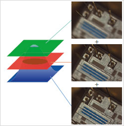
Tile multiple images to capture a single high-magnifi cation, wide-area image. Because the images are tiled on the basis of coordinate data, the system is capable of producing highly reliable images.
The EFI function is eff ective for obtaining images that are well-focused throughout on samples with an uneven, complex surface shape. Generate a single image with focal points aligned in all positions.
Simply process multiple images with diff erent focal point positions while moving the Z-axis, or use the motorized model for automated image composition.